Chain in surveying - Equipment used chain in surveying - Procedure in chain surveying
What is chain surveying :-
Chain Surveying– Chain surveying is used for measuring only horizontal linear measurement.
Chain surveying is suitable for open ground and small extent area. Chain in surveying only simple details are know. The principle of chain surveying / chain triangulation is to provide a skeleton or framework consisting of a number of connected triangles. For better result, frame work should consist of triangles which are as nearly equilateral as possible.
In this Content :-
1. Chain in surveying definition
2. Types of equipment used in chain surveying
3. Ranging
4. Chain surveying station.
5. Factor affecting survey station selection in surveying
6. Types of line used in chain surveying.
7. offsets of chain in surveying.
8. Instrument used for drawing offsets.
9. Working in chain surveying in offsets.
10. Procedure of chain surveying.
11. Obstacles in chain surveying.
12. Field book mention chain in surveying.
Types of equipment used in chain surveying :-
01. Chains
02. Arrows
03. Peg
04. Ranging rod
05. Plumb bob
06. Hammer
01. Chains – In chain surveying chains are the most important equipment for the procedure of survey. The chain are the straight links of galvanised mild steel wire bent into rings at the ends and joined each other by three small circular or oval rings. The length of the links is distance between the centre of two consecutive middle rings. While the length of the whole chain is measured from the outside of the one handed to the other side of the other handle.
Types of chains used in surveying :-
i. Metric chain
ii. Gunter’s chain / Surveyor chain
iii. Engineers chain
iv. Revenue chain
i. Metric Chain – Metric chain are generally of 5 m, 10 m, 20 m, & 30 m, length. In details about the metric chain
In 5 m, 10 m, chain tallies are provided at every one meter length to take reading easily while these tallies are provided at every 5 m length in 20 m and 30 m chains. In 20 and 30 chains, Small brass rings are provided at every one meter length accept where tallies are provided.
ii. Gunter’s Chain – A gunter’s chain is 66 feet long and consist of 100 links, each link 0.66 feet long (7.92 inches). It was originally adopted for convenience in land measurement since 10 square chain are equal to 1 acre, also while measuring linear measurement.
10 gunter’s chain = 1 Furlong
80 gunter’s chain = 1 mile
iii. Engineers chains – Being 100 feet long and consist of 100 links, each link being 1 feet. At every 10 links brass tags are fastened with notches indicating 10 links segments.The uses of engineers chain are generally measured to Feet.
iv. Revenue chains – The Revenue chain is 33 feet long and consist of 10 links each link being 2 1/16 feet long, the chain in surveying used for measuring
NOTE- Chain may be get altered (it’s length) due to continuous using either it’s length is being shortened due to bending of links or it’s length gets elougated due to starching of links or opening of the connecting rings. Thus don’t give accurate measurement.
So; it chain should must be tested time to time either with the reference to a tape or by measuring with a permanent test gauge.
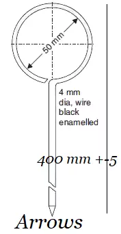
02. Arrows – These are the marking pens made of steel wire and generally 10 arrows are provided with a chain survey. Length may vary from 25 mm to 50 mm but specified length as per IS-Code. the arrow is made sharp and other end is bent into a loop or circle for facility of carrying. The uses of arrows
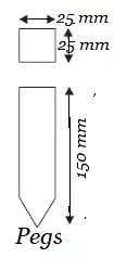
03. Pegs – Pegs are used to mark the position station or terminal point of a survey line. They are driven in the ground with the help of the wooden hammer and kept 4 cm above the ground surface. The dimension of pegs are generally 15 cm long and 3 cm squared in the top.
04. Ranging rods – They are 2 m – 3 m high rods of steel or well seasoned wood used the ranging of point. They are painted in alternate colours of the band either white & black, white & red or black, white and red in succession. band is of length 20 cm, so that can be used for the rough measurement of smaller length 2 m ranging rod being more common. They are circular or octagonal in cross-section of three cm diameter and are almost invisible at a distance of 200 m.
They are provided with yellow or white flag 0f 30 – 50 sq. cm area tied near it’s stop.
Ranging poles – They are similar to ranging rod expect they are very high in length (4 m–8 m) they are similar to ranging rod and are used in very long survey lines or in hilly reason. The foot of each pole is sunk about 0.5 meter into the ground.
05. Plumb bob – These are used for centering i.e; to transfer the point exactly to the ground station. while instrument campass level, plane table, theodolite,chain in surveying etc,
While chaining along sloping ground, it is used to transfer the point exactly on the ground.
06. Hammer - General used.
Term's used in chain surveying :-
Ranging – Ranging is the process of establishing or fixing intermediate points between two fixed points (to be surveyed) in a very straight line is called ranging.
When length of line to be surveyed is with in chain length and tape length, Then there is no difficult but when the length is greater than the chain length, when the intermediate points should be fixed in a well straight manner by ranging.
Ranging are classified :-
(1) Direct ranging - When the two end of the surveyed line are intervisible then direct ranging are possible.
Direct ranging is further classified into two types :-
Ø Ranging by eye.
Ø Ranging by line ranger.
Ranging by eye - Let A and B is the two end point of a surveying and P is the intermediate point establish on the ground. Surveyor stand for the station A and the one ranging rod is erected at the point B. Then assistance are goes with another ranging rod are approximately stand for the line AB and the surveyor instruct the assistance to move transverse to the chain line, till he is line in the AB. similarly more then intermediate points are established by the above procedure.
Ranging by line ranger - A line ranger either consist of two plane mirrors or two right angled isocallous prism. Placed one above other where diagonal are silvered so as two reflect incidental ray.
The range a point ‘P’ two ranging rods at the ends A & B and the surveyor at P hold the line ranger very near to line AB.
The lower prism ABC receives the ray from, A which are reflected back towards the observer similarly, the upper prism DCB receives the ray from B which are reflected back by it,s diagonal’s towards observer thus, the observer views the images of ranging rods A & B which may not be in same vertical line.
The surveyor moves with the line ranger. The point where two images coincide in the line ranger is the point in the line with two fixed ranging rods.
Indirect ranging - This ranging is done when the two points to be surveyed are not intervisible to each other due to high levelled ground in between or due to very long distance.
In such case, ranging is done indirectly by selecting two intermediate points P & Q very near to proposed survey line. Such that from P, both Q & B are visible and from Q both P & A are visible.
(2) Indirect ranging – This ranging is done when the two points to be surveyed are not intervisible to each other due to high levelled ground in between or due to very long distance.
In such case, ranging is done indirectly by selecting two intermediate points M & N very near to proposed survey line. Such that from M, both N & B are visible and from N both M & A are visible.
Code signals of ranging :-
Signal by the Surveyor | Action by the Assistant | |||
1. Rapid sweep with right hand | Move considerably to the right | |||
2. Slow sweep with right hand | Move slowly to the right | |||
3. Right arm extended | Continue to move to the right | |||
4. Right arm up and moved is the right | Plumb the bob is right | |||
5. Rapid sweep with left hand | Move considerably to the left | |||
6. Slow sweep with left hand | Move slowly to the left | |||
7. Left arm extended | Continue to move to the left | |||
8. Left arm up and moved is the left | Plumb the bob is left | |||
9. Both hand above head and then brought down | Correct | |||
10. Both hand extended forward horizontaly and the hands depressed briskly | Fix the rod | |||
Chain surveying station :-
· Main station
· Subsidiary or tie station
Main station – Main station are the end of the lines, which command the boundaries of the survey, and the lines joining the main station are called main surveying lines or the chain surveying lines.
Subsidiary or tie station - Subsidiary or tie station are the point selected on the main survey lines, where it is necessary to located the interior details such as fences, hedges buildings etc.
Factor affecting survey station selection in surveying :-
a. It is clearly visible.
b. The line are level ground as far as possible.
c. Main line are triangles.
d. Each triangles are must be provide with check line.
e. Avoid the obstacles through main survey line.
f. Getting short offset.
a
Types of line used in chain survey :-
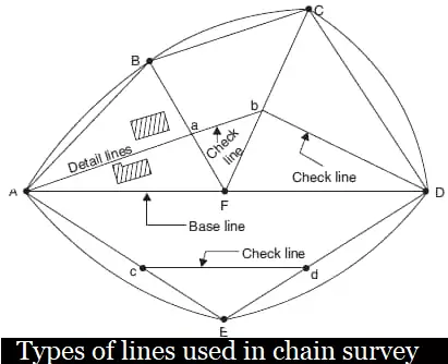
Base line – It is a main and longest line, which passes approximately through the centre of the field. All the other measurement to show the details of the works are taken with respect to this line.
Check line – A check line also termed as proof line is a line joining the apex of a triangle to some fixed point on any two sides of a triangle. It is measured to check the accuracy of the frame work. The length of check line measure in the field must agree with its length on the plan.
Tie lines – A tie lines joins the two fixed points on the main surveyed line. It helps to check the accuracy of surveying and to located the interior details of nearby the objects. In framework more tie lines are provided depending upon the circumstances.
Offsets of chain in surveying :-
Offsets are the lateral measurement from the surveying lines to fixed the position of different objects with respect to the survey lines.
Types of Offsets :-
1. Perpendicular offsets
2. Oblique offsets
1. Perpendicular offsets - When the angles of offsets is 90 degree . It is called perpendicular offsets.
Perpendicular offsets is also categories two types :-
(a) 3 - 4 - 5 method (Pythagoras theorem)
(b) Swing method
(a) 3 - 4 - 5 method - This method is used to draw perpendicular offsets & is based on the principle of pythagoras theorem.
(b) Swing method - This method is also used to draw perpendicular offsets in chain in surveying and other survey. It is based on the principle that the shortest distance any two point is nothing but the perpendicular distance.
2. Oblique offsets - When the angles of offsets is any other angle but not be 90°. It is called oblique offsets. Oblique offsets is very used chain in surveying .
Instrument used for drawing offsets ( chain in survey )setting out right angles :-
1. Cross staff
2. Optical square
3. Prism square
4. Site square
1. Cross staff - Cross staff are also available for three types :-
a. Open cross staff
b. French cross staff
c. Adjustable cross staff
a. Open cross staff - Since the open cross staff is light and strong so it is more commonly used to draw the offsets at right angle.
b. French cross staff - It is used for setting an offsets at the angle of 45 degree.
c. Adjustable cross staff - It is used for setting an offsets at any angle.
2. Optical square - If it is more accurate then the cross staff and is used for setting out accurately the long offsets. it is a smaller compact hand instrument based on the principle of reflection.
The principle under laying the construction of reflecting instrument may be started as if these are two plane mirror whose reflecting surfaces makes a given angle with each other and if the ray of light is reflected successively from both of them then the angle between the first incident ray and last reflected ray is twice the angle between the two mirror.
In case of a optical square the angle between the first incident ray and the last reflected ray is 90°
3. Prism square - Prism square is a modern and precise instrument and used for a similar to the optical square.
4. Site square - It is used in conjuction with a datum rod screwed into the base of the instrument. It connected with two telescope.
Working in chain surveying in offsets :-
A ray from ranging rod at Q passes through lower unsilvered portion of mirror at B. and is seen directly by eye at silt E. Another ray from the object at P is received by the mirror at A and is reflected towards the mirror at B which reflected towards the eye thus, the images of P & Q are visible at B.
If both the images coincide each other the line P will be at right angles to each other then all points are checked and established.
Procedure of chain surveying :-
(1) Reconnaissance – The preliminary inspection of the to be surveyed is called reconnaissance. The surveyor inspect the area to be surveyed, survey or prepares index sketch or key plan. He should also investigate the difficulties of plotting the survey line and other work.
(2) Marking station – Survey fixed up the require no of stations at the place from where maximum possible station can be plotted.
Some operation :-
a. a. Fixing of ranging rod or poles.
b. Driving pegs.
c. Making a cross (X) if ground is hard.
d. Digging & fixing a stone.
(3) Then selected the way for passing main line. Which should be horizontal and clean as possible and should passed approximately through the centre of work.
(4) The ranging rods are fixed on the station.
(5) After fixing the stations, chain in could be started.
(6) Make ranging where ever necessary.
(7) Measure the chain edge and offsets.
(8) Enter the observation and measurement in the field book .
Obstacles in chain surveying :-
(1) Obstacles to ranging.
(2) Obstacles to chaining.
(3) Obstacles to both ranging and chaining.
Field book mention chain in surveying :-
A field book is a standard oblong for pocket book where all the observation and measurement taken during chain surveying is to be recorded.
It is 200 m long and 120 mm wide. It is open length wise . It is a two types.
i. i. Single line field book
ii. Double line field book
The pages of a single line field book have red line along the length of the paper in the middle of the width (indicating the chain line) and all the chain edges are written across it. The space on either side of the line is used for sketching the objects and for noting offsets distance.
The chain edges in the double line field book are to be written with in these two lines indicating the Chain line.


0 Comments